
Pump Housing Heat Conduction and Finite Element Mesh Verification
01
Project Background
Holes, cavities and thin walls make a housing difficult to represent with a single thermal resistance. Changes in wall thickness, heat-source location or distance to a prescribed-temperature boundary alter heat-flow paths, so reusing an earlier temperature conclusion can miss local risks.
The example examines steady-state heat conduction in a three-dimensional pump housing with internal heat sources and specified boundaries. Engineering use requires traceable CAD, material parameters, heat-source definitions and boundary evidence, with contact resistance, convection or transient processes added as needed.

02
Geometry, Materials and Technical Approach
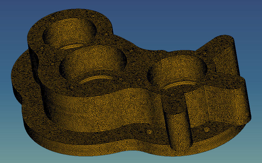
Preserve the original STEP file and create a separate analysis geometry, checking small faces, duplicate faces and open solids. Review element quality around holes, thin walls and changing curvature rather than judging resolution solely by element count.
The material register records conductivity, density and heat capacity with sources and units, identifying which properties enter the steady-state equation. Distinguish mass-specific heating, volumetric heating and total power. Prescribed temperature, heat flux and convection conditions are separate definitions, and conflicting boundary assignments must be resolved before solving.
03
Implementation and Comparison Runs
First use simplified geometry and one heat source to check units, the temperature reference and constraint interpretation, then restore the full housing. Retain each run’s mesh, material table, boundary identifiers and logs so post-processing uses the current project rather than a cached result.
Then compare refined meshes and alternative boundary assumptions. Evaluate temperatures at matching locations, hot regions and overall heat balance, separating discretization effects from boundary effects. Compare design alternatives only after the results are sufficiently stable under agreed checks.
04
Deliverables and Acceptance
Deliver analysis geometry, the solver project, material sources, boundary tables, mesh comparisons and a result explanation. Temperature plots include units, legends and run identifiers. For downstream development, agree result formats, field names and coordinate systems.
Acceptance reloads the project in a clean environment and reruns one baseline case, checking agreed locations and output fields. Product decisions require suitable measurements or trusted benchmarks, with numerical error, measurement uncertainty and modeling simplifications recorded separately.
05
Scope and Verification Boundaries
The method supports preparation and review of conduction analyses for housings, brackets and similar solid components. The original images show a tutorial model and do not establish cooling capacity, seal life or assembly reliability for a physical pump.
For fluid cooling, temperature-dependent material properties or thermal deformation, add the relevant equations and coupling interfaces and define acceptance conditions for each physical domain.
06
Implementation Outcomes
The workflow links temperature assessments to specific geometry, meshes and boundaries, making rerun scope clearer after design changes and reducing version confusion and repeated setup. Any reduction in prototype iterations requires project evidence.
Assess efficiency through preparation time for comparable conditions, successful project reruns and rework caused by boundary issues. Assess analysis quality through mesh sensitivity and deviation from measurement points.