
Rail High-Voltage System Logic Modeling and State Simulation
01
Project Background
Rail high-voltage control involves commands, equipment states and cross-component signals. Structural drawings alone do not establish action order, while interface buttons can obscure the difference between issuing a command and receiving equipment confirmation. Behavioral models make that distinction explicit.
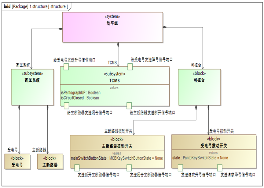
This method case models pantograph movement and main circuit breaker switching around the structure, signals and internal connections of a train high-voltage system, supporting design-stage logic checks and reviews.
02
Technical Approach and Simulation Scope
Separate control roles, equipment roles and interaction signals. Internal connections express signal paths and state behavior represents responses. Commands, confirmations and display state remain distinct rather than overloading one display variable with several meanings.
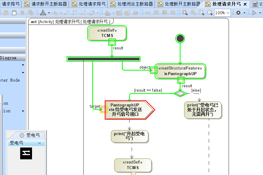
Defined events drive software logic while recording entered states, evaluated conditions and output actions. Voltage, current or mechanical dynamics require separately validated physical models; logic transitions alone do not establish equipment performance.
03
Implementation and Scenario Organization
Decompose one operation into a command, preconditions, response and confirmation, assigning signal owners. After the nominal case, add agreed cases such as missing feedback and unmet conditions. Undefined rules return to requirements clarification.
Freeze model version and initial state for each execution and retain event sequences and verdicts. After behavior changes, replay affected scenarios, compare differences and explain them. The interface supports observation; inspectable state and event records support conclusions.
04
Deliverables and Acceptance
Deliver the logic model, port and signal dictionary, initial configuration, scenario inputs, execution records and issues. The receiving team should reproduce a nominal and an exception scenario in the agreed environment and trace records back to model elements.
Acceptance checks requirement-scenario links, transitions against agreed conditions and traceable outputs. Conclusions without input or feedback evidence remain unverified. Electrical safety, physical response time and equipment reliability are outside pure logic-model acceptance.
05
Applicability and Next-Stage Integration
Applicable to control design reviews, interface clarification and logic checks before integration. Field use also requires equipment testing, safety validation and applicable certification.
Hardware-in-the-loop or site testing requires renewed agreement on interfaces, test permission, physical protection and professional responsibility. Simplifying software assumptions travel with the model and must not silently become physical equipment attributes.
06
Implementation Outcomes
Logic simulation makes cross-component conditions and feedback processes reviewable and replayable, reducing ambiguity and providing consistent scenario inputs for integration.
Track design-stage improvements through logic issues found during review, issue reproduction setup time and regression scenario coverage.